Evolution of the Floating Connector to the Z-Move
IRISO was an established in 1966 and soon after developed various connection methods and jumpers for use on printed circuit boards (PCBs). IRISO is about creating value and contributing to the improvement of customer’s designs leading the way to the future. This is accomplished by supplying innovative products of high quality.
A leading manufacturer of connectors, IRISO is dedicated to coming up with new solutions. The company works to maintain long-term growth while providing communication and transparency. With the digital age moving toward more technology and computerization, the need for reliable connectors is paramount.
The Need for a Reliable Connector
The automotive industry is where the need for floating connectors started and that need continues today. The industry’s increased reliance on technology can be seen both under the hood and in the use of computers and sensors. More recently, the use of advanced digital sensors on the exterior of the car to help with safer driving and higher autonomy has grown.
Other industries such as the medical and industrial markets also have seen an increase in digital technology that requires reliable connections. Medical devices can experience a lot of shock and vibration during transit or field work. Medical devices also need to be exceptionally reliable and precise as lives are counting on it.
The industrial environment has likewise seen a revolution in computing through such things as programmable logic controllers and robotics. These devices can also experience harsh conditions, often from production lines and general operation. Once again, the need for a high reliability connection is important as a failure could stop production or cause injury.
Problems with Traditional Connectors
Traditional board-to-board connectors have pins that are soldered directly to the circuit board and are held together with a plastic housing. These connectors work adequately as long as the mated PCBs are free from stresses, such as misalignments, stack-up tolerances/skewed relative position of the mated PCBs. A common issue with these connectors is that they place a lot of stress on the PCB and on the solder connections. Traditional board-to-board connectors simply aren’t designed against stresses and this often leads to failure. Automated assembly can create the issue of coordinating correction and potential crush mating by the robotic mating force. Another failure of traditional connectors is that movement over time can wear away the contact surfaces. This wear, called fretting, leads to oxidation between the pins and increased resistance. Based on these shortcomings and customer feedback, it was obvious that a new design was required.
The Market for a Reliable Connector
In the vehicle cabin, electronics are much more sophisticated when it comes to information and entertainment. Consumers want their cars to give directions, connect with phones, to help in an emergency, control cabin climate, analyze weather and provide diagnostics. A vehicle system that used to just be a radio has become a computer to satisfy an ever-increasing need for information and entertainment—infotainment.
Under the hood, the need for better vehicle gas mileage and performance has become a legal necessity. Computer control units in cars, called ECUs, control engine performance ranging from fuel injection and spark and valve timing to many other parameters. With the introduction of drive-by-wire and electric vehicles (EVs), under-the-hood computers are getting more complex. Just about everything in the vehicle is plugged in through a connector.
Many vehicles now come with an array of sensors to enable safer driving. Some of the electronics in vehicles now include blind spot warning, automatic emergency braking, forward collision warning, lane departure warning, lane centering and adaptive cruise control, to name a few. All of these applications have a renewed need for a reliable connector.
The Floating Connector
Floating connectors got their start in infotainment equipment due to reliability issues of the original equipment. In the early days of infotainment, only high-end cars had this capability. Unfortunately, these connectors could not withstand the rigors of the automotive environment and were prone to failure. This was an unwelcome issue in any car, let alone luxury cars. The system running these infotainment consoles is contained in a box tucked away somewhere under the dash. To achieve the level of sophistication required in a small footprint, a stacked PCB configuration is often used. This method allows manufacturers to spread a circuit out over a few PCBs, usually two to four. Connecting these boards together are board-to-board connectors with a large number of pins for the various signals.
It turned out that one of the main failures with early infotainment systems was the board-to-board connector. Stresses were causing solder joints and the connectors to fail, so the need for a new board-to-board connector was obvious and that led to the floating connector.
What is a Floating Connector?
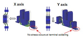
Floating connectors are designed such that the pins are not simply straight pins but instead have a built-in spring. This design allows for movement in the X and Y axes and solves many of the issues with traditional connectors. The spring takes the stress off of the solder joints and contact pins.
Resonance between PCBs is another issue seen with vibration; certain frequencies of vibration will cause the boards to experience higher movement due to the natural flex of the PCB. The floating connector is designed such that horizontal vibrations will have no effect on the contacts or the solder joints.
How the Floating Connector Works
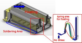
Floating connectors work much like the leaf springs in a vehicle. The pins are formed with a bend that flexes. This spring action allows the pins to move left to right. The housing in a floating connector is also a floating element that is suspended by the contact pins. This floating design enables the connection to maintain the proper mating force during vibration.
The Evolution of the Floating Connector, the Z-Move Connector
The Z-Move connector is the next step in the floating connector design. This connector design has all of the benefits of a traditional floating connector but can also withstand movements in the Z direction. This means the connector can tolerate X (pitch), Y (vertical) and Z (mating) vibrations or misalignment. This is an important difference as vibration and misalignment often don’t occur in only two directions. The addition of the Z axis adds higher reliability than other floating connectors. The Z-Move connector also eliminates problems with broken pins during assembly.
When two PCBs are stacked or otherwise assembled with a connector, there will be various forces involved. The forces may come from many different sources such as the flexing of the boards or improper mounting. Some of these forces are constant while some may shift. The Z-Move connector can adjust and absorb the forces such that no strain is placed on the connector.
This solution works effectively when used for safety applications such as vehicle powertrain and sensors. The Z-Move connector is also a perfect fit in medical and industrial technology.
How the Z-Move Connector Works
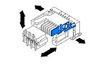
In the Z-Move connector, the contacts are designed with 3 dimensionally calculated, various diameters and thickness that allows the contacts to move with more freedom with even a slight force applied. Because of the terminals’ design with mechanical geometry, studied from a number of experiments, it maintains a proper contact force on the pins while eliminating issues with stress vibration, contact wear and misalignment.
The issue of contact wear happens over time due to the vibration of the mating pins. The up and down jostling in a traditional connector will cause the contact mating surfaces to slide, causing fretting. Traditional connectors will eventually have issues while the Z-Move connector will not, as it protects against mechanical vibration from all directions, and will do so over its lifetime through repeated vibration. This protection persists even in challenging environmental conditions.
The Z-Move connector is the next step in connector design that is available now to solve contact reliability problems. For designs that may experience reliability issues, manufacturers should consider switching to the latest in connector technology, which is only the Z-Move connector.
Category: Product News